PowerVR TBDR - Deferred Rendering
Friday, Jan 29, 2016 · 2700 words · approx 13 mins to readIntroduction
What follows is a republishing of an article I wrote for Imagination’s company blog. Originally published on 28th January 2016, it covers the second part of how a modern PowerVR TBDR implementation works: deferred rendering.
In my previous article, I wrote about how our GPU architecture works. It’s a novel architecture which works unlike any other, and we call it a tile-based deferred renderer, or TBDR. The basic premises are simple enough in concept.
First, we split the screen up into tiles to make them simpler to process and small enough to fit entirely on the GPU, reducing how much we need to access memory. That’s the part I explained first, so if you haven’t read it then please go do so!
The second part takes the information generated in the first part — lists of primitives for every tile we want to render — to defer the rendering of subsequently generated pixels as much as possible, so we render as few of them as we can get away with. Let’s see how that works in hardware.
The parameter buffer

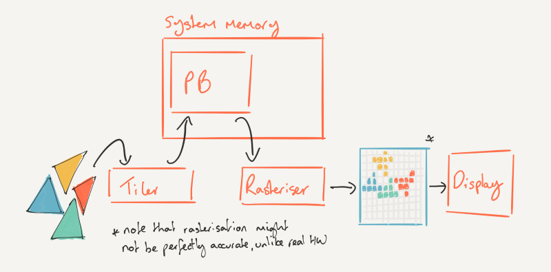
The last thing the hardware did in my first article was fill the parameter buffer (PB). To recap, the PB is essentially a packed list of tiles, filled with other lists of transformed geometry that contribute to those tiles, as efficiently as the hardware is able to figure it out. Remember we don’t use simple, inefficient methods of figuring out which tiles a primitive might contribute to. We actually work it out, tile accurate, so we don’t waste time processing primitives that don’t actually contribute to the tile in the end.
So the GPU has built that intermediate data structure and it’s full of lists of lists of triangles. Now what? We need to rasterise of course, and turn those triangles into pixels, and get those pixels shaded by the core. For our architecture, rasterisation is more sophisticated than it is in others: key things that drive the efficiency of our GPUs are baked into this part of the pipeline, so let’s go through it all step-by-step.
As an aside, it might surprise some readers to discover that rasterisation doesn’t just happen in a simple monolithic block called the rasteriser. In all GPUs, big and small, it’s a tight dataflow-oriented pipeline made up of numerous sub-blocks, run in stages. Balancing them all without any becoming a bottleneck to your throughput is difficult, and because of the nature of the task at hand it’s much more suited to fixed-function logic than punting to whatever programmable shader core you might have.
Fetching the PB back into the core
First, we need to fetch the tile lists back into the core from memory, and then parse them to get state, position data and some control bits to help the GPU work on the geometry properly. The data could be compressed, so the block that’s responsible for reading it back in, which we call parameter fetch, is also able to decompress the data to be worked on. Because of the kinds of memory accesses this block makes, it has to be able to tolerate some amount of memory latency for fetches, so it can do some prefetching and supports burst reads from memory to help get the data into the core again, from the PB. So far so good.
The edge equations
So now we’ve got the triangles streaming back into the core, we need to start the process of turning them into pixels. Remember that we’re working with geometry in 3D space, not 2D space, yet your screen is a 2D planar thing. So we need some way of mapping the renderer’s computed view of 3D space to our 2D screen.

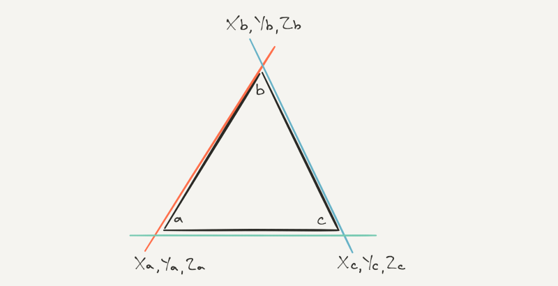
The bit of the hardware that accepts a primitive from the parameter fetcher, on our road to rasterised pixels, is responsible for setting up a trio of equations that define the edges of the triangle, so we have a representation of where it is on the screen that’s more than just points. Because it requires some computation to do so, this bit of hardware has its own dedicated, and actually pretty complex, floating point units in a fixed arrangement.
There’s actually not much else going on here other than computing the edge equations for the triangle. There’s a spot of depth biasing which helps when triangles share exact depth values, so they don’t fight with each other in terms of which one should be visible, and some angle calculations to give further blocks a better idea about the makeup of the geometry.
The plane equation
Now we have a set of edge equations, combining to define the triangular geometry as if it were a prism in 3D space. That’s maybe counterintuitive to imagine and picture in your head, because you never really see it in true 3D and you’d need some imaginary lines to help you visualise it anyway!
We then need to take a 2D slice through that prism to basically flatten it and figure out what bits of the prism end up as the 2D representation of the triangle we want on our screen. It’s an important milestone for us to get to in hardware, so to make it happen we need a fourth equation that defines that planar slice through the prism defined by the edge equations.
We evaluate that fourth equation in the hardware, giving us our planar slice, which we can work on to map to the pixels in our tile. Let’s talk about that screen tile a bit to help explain it.
Tile size
There’s a set of trade-offs to be made in any tiled architecture, between the tile size and what storage you need for it. In our case, we need some storage for the PB, which keeps a list of triangles for the tile. That lives in system memory. Then we need some storage inside the GPU, on the chip, to process the pixels in that tile.
So think about two theoretical tile sizes, one four times as big as the other (twice as big in X and twice as big in Y), and we’re rendering at 1080p say. Obviously we need more tiles if they’re smaller, so that means more tile lists in our PB, but probably fewer triangles will intersect each of those tiles, and we need less storage on the GPU to process them. The converse is true for the bigger tiles. We need fewer tile lists because there aren’t as many tiles, but the number of triangles in each one is probably going to go up on average, and we’ll need 4x the storage on the GPU because each tile now has 4x the pixels.
That’s why, at least for our architecture, the tile size tends to be small; there’s more that John and his team consider when they’re figuring out the optimum size, of course, but those are the biggest factors. We’re currently at 32x32 pixels for regular rendering on Rogue, but it’s been smaller in the past on SGX, and also non-square for that architecture too.
MSAA
I say regular rendering, because there’s one more thing to consider: multisample anti-aliasing. I won’t cover what MSAA is — it’s a future article in and of itself — but it improves image quality when enabled because it generates more per-pixel samples than are produced in regular rendering (there’s usually just one), and uses that extra data to help remove high frequency signals in the image with a filter over the samples.
So if we’re generating more data for each pixel, we need some storage for it. There are a few ways you can go about that. One is to store the extra samples in system memory, which is generally how it’s done. The other is to use some storage on the GPU so that you don’t need to consume off-GPU bandwidth when you’re processing MSAA.
We take the latter route, dedicating some storage inside the GPU for the multisample data in order to increase efficiency and decrease external memory bandwidth. The form that memory takes is beyond the scope of this article, but it’s obviously part of the shader core somewhere so it can be accessed by the USC quickly.
Actually rasterising
Back to rasterisation inside that tile we just described. So for each incoming triangle that’s come out of the block that generates its edge equations, we evaluate those equations and the plane equation together in a block we call the Image Synthesis Processor, or ISP. The ISP is the heart of our GPU designs in many ways, because it’s where the deferred part of things goes on.
After evaluating the equations, we test the resulting representation of the triangle against each pixel’s sample location in the tile (or multisample locations if MSAA is on!) to see which pixels lie within the incoming triangle. At this point, we’ve finally rasterised: we flattened the triangle into 2D by evaluating the edge equations and after testing the result against the pixels in the tile, we know what area of the screen it covers.
Hidden surface removal
Hidden surface removal is where the true efficiency savings of our GPU really start to kick in. We’ve reaped some benefit from tiling, which lets us divide the screen up into bits we can easily fit onto the GPU. Keeping the data on the GPU while we’re working on it lets us avoid costly and power hungry memory accesses. But there’s more we can do.

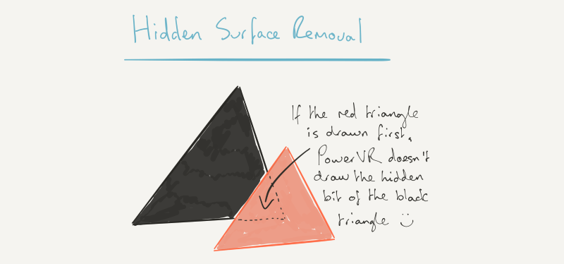
When we’ve rasterised the pixels, we test their depth (Z, in graphics parlance) against the depth buffer. If the depth test — which is usually just “is it closer to the screen than the last value at that pixel location in the depth buffer?” — passes, we update the depth buffer with the new pixel value, and store some data that says, “this pixel in this triangle contributes to this tile”.
Now you can imagine that the result of that process is a set of data for the tile that only encodes the visible pixels that pass the depth test. It’s worth repeating, with emphasis. The output of the process is a set of data for the tile that only encodes the visible pixels that pass the depth test. Only the visible pixels.
What that saves in terms of processing is potentially very significant. It all works because we capture up front every draw call for a given render, before asking the GPU to do any work on it. On other GPUs, the driver will send commands to the GPU to do something as soon as a draw call comes in from the application. It doesn’t matter what was drawn before, if anything, or what will be drawn after, if anything. But for the cases where something, and potentially lots of somethings, are drawn before and after, there’s a potentially significant saving to be had. There are traditional ways to try and avoid the work on other architectures, similar to the way we do it in some cases, with an early depth test before pixel shading. But the test is often coarse, rather than pixel-accurate like ours.
We wait until we have all of the draw calls that affect a given buffer, before asking the GPU to do anything. That lets us capture all of the geometry that will affect rendering to that buffer, letting us do our tiling and then HSR afterwards, throwing as much unnecessary work away as we possibly can.
For opaque geometry, that is very powerful, and I’ll come back to it briefly at the end.
Transparency
Obviously there’s a hurdle for the ISP to get over when transparent objects are encountered. The way we handle transparency is fairly straightforward, costing us a bit of efficiency. When a transparent object makes its way into the ISP from the prior block, we effectively stop what we’re doing in the ISP at that point and flush all of the pixels passing the depth test directly into the shader core to be processed. Why? Because we have a transparent thing to blend on top, we need to know what value to blend with.
So we empty the ISP into the USC (or the USSE in SGX), run all of the shading for the visible opaque stuff it had encountered, and update the buffer with the final pixel values so we can blend on top. But we wait at this point, to see what else is coming in to the ISP next, because we need to preserve API submission order to meet all current API specifications
If we encounter another transparent object again, after one that’s just come in, we flush again to guarantee correct rendering. However if an opaque object comes in that covers all of the transparent object we just encountered, by passing the depth test, we just keep going.
So it all depends on what gets rendered in what order, to determine how much of that flushing causes efficiency to bleed away. Hats off to immediate-mode renderers: they don’t care about this type of rendering. They’ll blend all day long, at the cost of bandwidth. But in our architecture which is designed to save as much of that as possible, it’s a trade-off in raw performance that we have to make.
It’s why, if you’ve ever seen our developer recommendations documentation, we ask developers to do their transparent stuff last!
Parallelism
A little bit on parallelism before I wrap it up. Because we work tile at a time and they’re independently binned, you can imagine that it’s reasonably trivial for us to parallelise in the hardware at this level. Say we have a Rogue configuration with two front-ends. We just put an arbiter in front that assigns each one a tile in the list to work on, in parallel, and off they go together at the same time, working through that whole process I just described.
What actually gets saved
To wrap up, I’ve talked about the HSR part being the biggest efficiency saving thing we do in our architecture. But what kinds of savings are realised by keeping it all on chip and only processing visible pixels? For starters, all of the texture and target render buffer ingress and egress bandwidth during pixel shading, that would have been consumed by having to render those pixels. Pixel shading takes textures as input, and it needs somewhere to write the final values at the end. And for things like deferred shading, we can potentially create and consume the entire G-buffer on chip (if it fits in the per-pixel space we have!) without an external memory access.

We also save all of the pixel shading arithmetic operations for the pixels we threw away in the ISP: modern shaders are hundreds of cycles long, and the USCs are major consumers of power in the design. On top of that, while the USC is running a shader program it also needs to read and write its internal registers to store intermediate values, before the final one is written to the tile memory. Register access consumes internal register file bandwidth and a decent amount of power.
So that’s potentially hundreds or thousands of ALU operations and register reads and writes that we don’t have to do. It’s hard to overstate just how much of a benefit it is to only have to light up the USC for the pixels that will actually contribute to what you see. Our big power advantages versus our competitors are in large part because of this mechanism, driven by our ISP and realised by the later stages of the pipeline.
And in the products where you find our GPUs, that power advantage is critical to your enjoyment and use of your phone, tablet or smart watch. In fact, any device that needs a power efficient GPU to make the most of a battery.